* Add pattern method to Pressure Advance dialog

* Convert calib_pressure_advance to more unique calib_pressure_advance_line

* Share move_to function with PA lines and patterns

* Add PA pattern to calib.hpp

* Implement move_to(Vec3d). Combine with Vec2d version

* Add call to PA pattern in GCode.cpp

* Add helper functions

* Add directionality to draw_digit

* Extract shared number drawing variables

* Extract convert_number_to_string function

* Use in-class initializers for pattern variables

* Add max_numbering_height function

* Add helper functions

* Extract shared delta helper functions

* Add pattern generate_test() and associated helpers

* Clarify use of math functions

* Remove unused move_to overload, accept move_to comments

* Add get_distance() and draw_line()

* Extract set_nozzle_diameter()

* Clean up and simplify

* Rearrange and clean up

* Start work on print_pa_pattern

* Complete basic draw_box function

* Add more helper functions

* Add struct for pattern config, more helpers

* Rearrange

* Add encroachment member variable

* Add structs to manage optional arguments

* Simplify optional arguments structs

* Update opt args usage. Finish draw_box function

* Complete print_pa_pattern function

* Reuse PA Line STL

* Fix forward declaration error

* Fix invalid comparison

* Fixing complier errors

* Make DrawDigitMode options more clear

* More compilation error fixes

* Yet more compile error fixes

* Fix incorrect default step value

* Handle top-level dialog changes, consolidate params definitions

* Add layer change G-code, set more print variables

* Simplify optArgs constructors

* Fix pattern drawing, minor misc. clean up

* Make draw_box() G-code comments more helpful

* Make more of draw_line() const

* Fix sequential number draw direction

* Extract shared e_per_mm function

* Fix misplaced decimal in PA Line

* Move short constructor into .hpp

* Fix inverted Y direction in pattern digit drawing

* Use placeholder STL to create needed layers

* Rearrange and clean up

* Proof of concept: Adding custom G-Code at layer

* Use new scaling method

* Reorganize Plater::calib_pa()

* Restructure calib

* New strategy for adding custom G-code

* Remove redundant invocation

* Use cube primitive as positioning handle

* Move logic to Plater

Modifications to model in GCode cancelled _do_export from within itself

* Consolidate m_starting_point and pattern_start functions

* Replace bed_center() with m_starting_point

* Fix and consolidate number tab creation

* Fix off by one layer bug

* Use correct bounding box

* Use Vec3d instead of Vec2d for m_starting_point and m_last_pos

* Add translate_starting_point function

* Vec3d fix

* Store CalibPressureAdvancePattern with model

* Formatting adjustments

* Move pattern when handle moves

* Improve const correctness

* Improve/fix pattern writer and config

* Fix speed setting bug

* Pass model into generate_gcodes to improve consistency

* Re-generate pattern on reslice

* Make pattern actually move with handle

* Fix overzealous m_last_pos initialization

* Use clearer function names

* Use correct model

* Remove unused member variable

* Don't hard-code print config settings

* Remove unused lines, formatting clean up

* Make sure set_key_value operates on existing keys

* Remove asserts which limited life of key/value set

* Update Calibration.md

* Update licensing info

* Actually use speed in draw_line

* Don't speed_adjust twice

* doc: Make width and speed settings used more clear

* Bugfix: Shouldn't need to move handle to see pattern

* Clean up

* Move mp_gcodegen into line method alone

* Fix wrong number thickness in PA Line

* Remove unnecessary middleman PatternSettings

* Give value of config to const m_initial_config, not ref

* Fix incorrect DrawBoxOptArg default

* Use line_width_anchor() for all of initial layer

* Use clearer function name

* Replace "anchor" with "first_layer" for better consistency

* Update Calibration.md

* Update Calibration.md

* Make number tab infill explanation more clear

* (Hopefully) fix missing origin

* Add GCodeProcessor tags

* Fully refresh config

* Don't store is_bbl_printer

* Move set_starting_point to private

* Don't constantly recreate GCodeWriter

* Use different step value for pattern test

* Remove redundant processor tags

* Label glyph G-code

* Fix comparison typo

* Set number print speed

* Fix mixed up draw_number parameter

* Don't use line_width_first_layer for pattern

* (Hopefully) fix temp tower generating PA pattern

* Start with pattern centered on plate

* Add gap between pattern and handle

* Fix overly persistent pattern

* Revert "(Hopefully) fix temp tower generating PA pattern"

This reverts commit 0aa1206886d57820799beaf62dc28b9b8e02545b.

---------

Co-authored-by: SoftFever <softfeverever@gmail.com>
12 KiB
- Flow rate
- Pressure Advance
- Temp tower
- Retraction test
- Orca Tolerance Test
- Advanced calibration
- Max Volumetric speed
- [VFA]
NOTE: After completing the calibration process, remember to create a new project in order to exit the calibration mode.
Flow rate
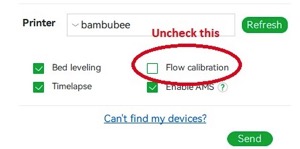
NOTE: For Bambulab X1/X1C users, make sure you do not select the 'Flow calibration' option.
 Calibrating the flow rate involves a two-step process.
Steps
-
Select the printer, filament, and process you would like to use for the test.
-
Select
Pass 1in theCalibrationmenu -
A new project consisting of nine blocks will be created, each with a different flow rate modifier. Slice and print the project.
-
Examine the blocks and determine which one has the smoothest top surface.
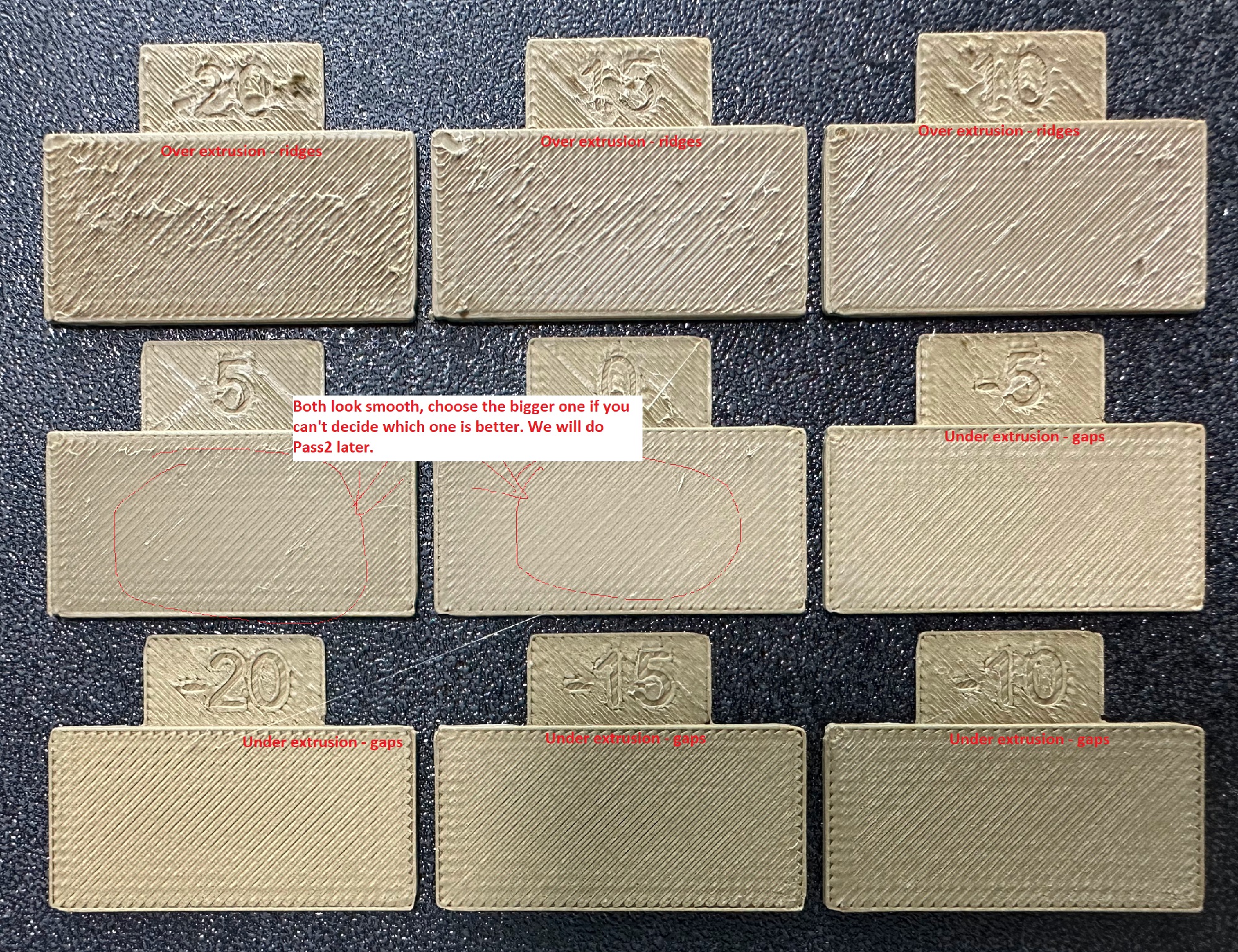
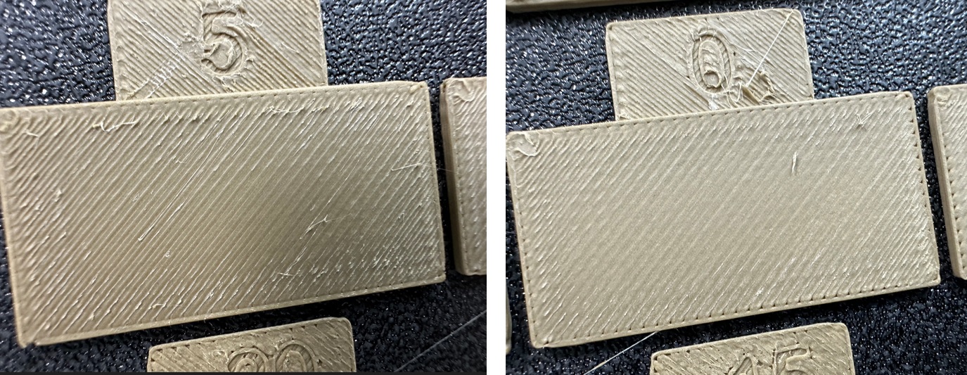
-
Update the flow ratio in the filament settings using the following equation:
FlowRatio_old*(100 + modifier)/100. If your previous flow ratio was0.98and you selected the block with a flow rate modifier of+5, the new value should be calculated as follows:0.98x(100+5)/100 = 1.029. ** Remember** to save the filament profile. -
Perform the
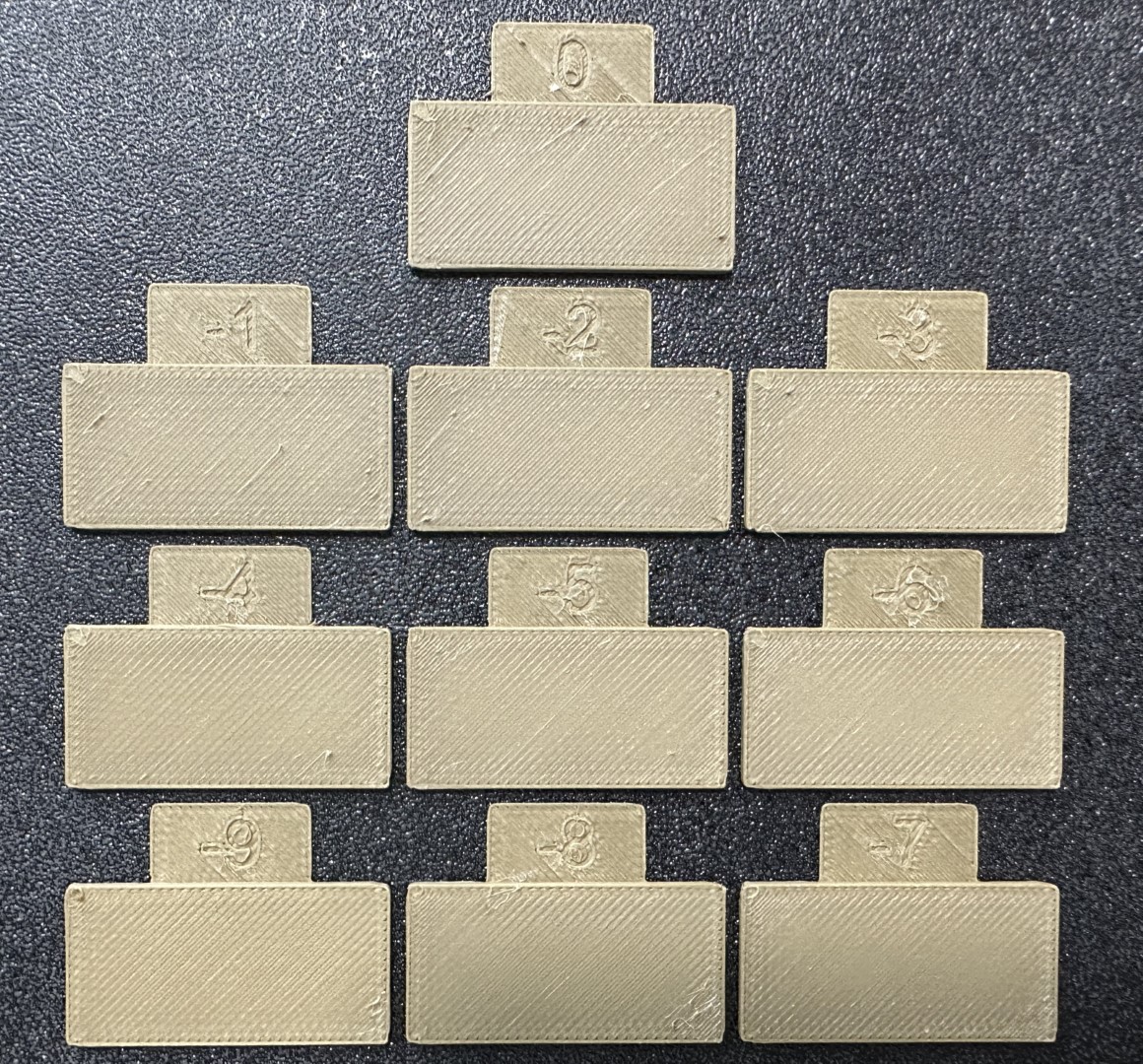
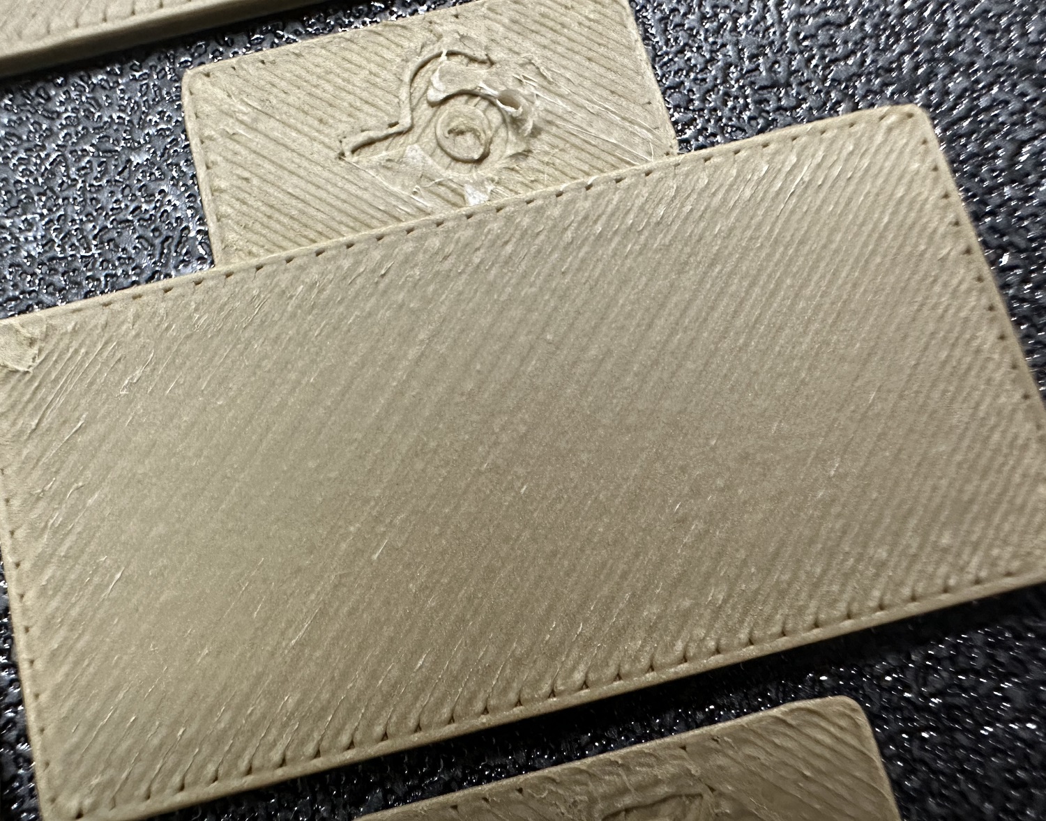
Pass 2calibration. This process is similar toPass 1, but a new project with ten blocks will be generated. The flow rate modifiers for this project will range from-9 to 0. -
Repeat steps 4 and 5. In this case, if your previous flow ratio was 1.029 and you selected the block with a flow rate modifier of -6, the new value should be calculated as follows:
1.029x(100-6)/100 = 0.96726. ** Remember ** to save the filament profile.

Pressure Advance
Orca Slicer includes three approaches for calibrating the pressure advance value. Each method has its own advantages and disadvantages. It is important to note that each method has two versions: one for a direct drive extruder and one for a Bowden extruder. Make sure to select the appropriate version for your test.
NOTE: For Bambulab X1/X1C users, make sure you do not select the 'Flow calibration' option when printings.
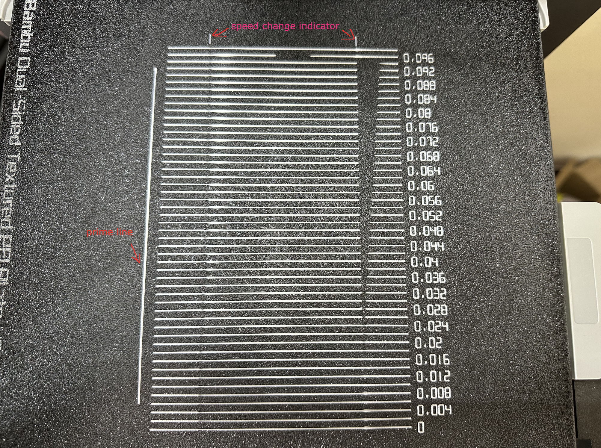
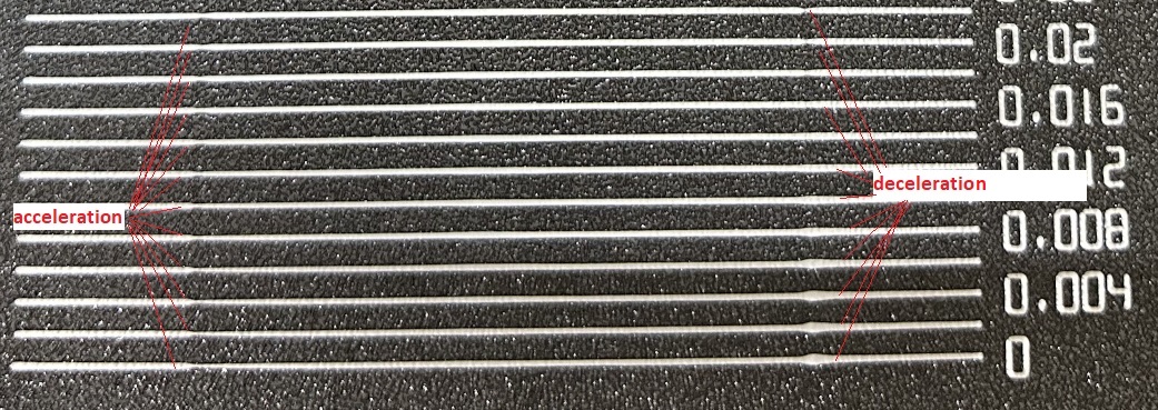
Line method
The line method is quick and straightforward to test. However, its accuracy highly depends on your first layer quality. It is suggested to turn on the bed mesh leveling for this test. Steps:
- Select the printer, filament, and process you would like to use for the test.
- Print the project and check the result. You can select the value of the most even line and update your PA value in the filament settings.
- In this test, a PA value of
0.016appears to be optimal.

Pattern method
The pattern method is adapted from Andrew Ellis' pattern method generator, which was itself derived from the Marlin pattern method developed by Sineos.
Instructions for using and reading the pattern method are provided in Ellis' Print Tuning Guide, with only a few Orca Slicer differences to note.
First and foremost, when you initiate the test, you'll only see a small rectangular prism on the plate. This object serves a few purposes:
- The test pattern itself is added in as custom G-Code at each layer, same as you could do by hand actually. The rectangular prism gives us the layers in which to insert that G-Code. This also means that you'll see the full test pattern when you move to the Preview pane
- The prism acts as a handle, enabling you to move the test pattern wherever you'd like on the plate by moving the prism
- The filament selected for the prism is also used for the test pattern
Next, Ellis' generator provided the ability to adjust specific printer, filament, and print profile settings. You can make these same changes in Orca Slicer by adjusting the settings in the Prepare pane as you would with any other print. When you initiate the calibration test, Ellis' default settings are applied. A few things to note about these settings:
- Ellis specified line widths as a percent of filament diameter. The Orca pattern method does the same to provide its suggested defaults, making use of Ellis' percentages in combination with your specified nozzle diameter
- In terms of line width, the pattern only makes use of the
DefaultandFirst layerwidths - In terms of speed, the pattern only uses the
First layer speed -> First layerandOther layers speed -> Outer wallspeeds - The infill pattern beneath the numbers cannot be changed becuase it's not actually an infill pattern pulled from the settings. All of the pattern G-Code is custom written, so that "infill" is, effectively, hand-drawn and so not processed through the usual channels that would enable Orca to recognize it as infill
Tower method
The tower method may take a bit more time to complete, but it does not rely on the quality of the first layer.
The PA value for this test will be increased by 0.002 for every 1 mm increase in height. (NOTE 0.02 for Bowden)
Steps:
- Select the printer, filament, and process you would like to use for the test.
- Examine each corner of the print and mark the height that yields the best overall result.
- I selected a height of 8 mm for this case, so the pressure advance value should be calculated as
0.002x8 = 0.016.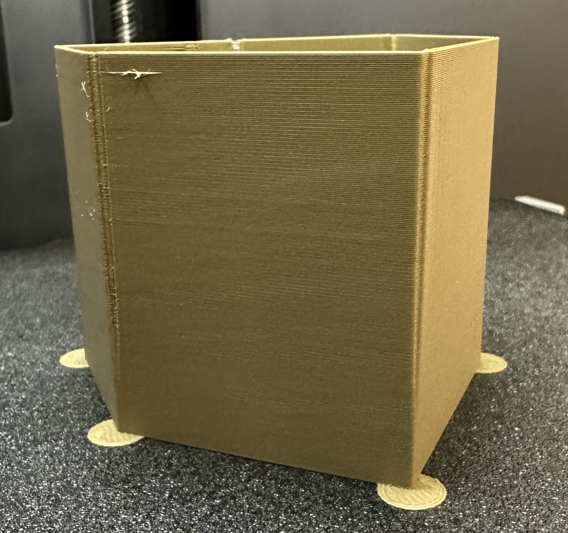
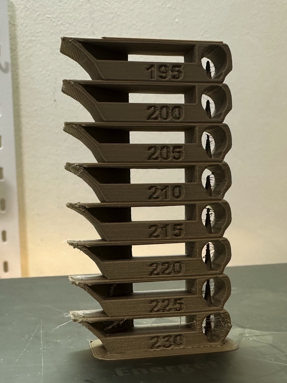
Temp tower
Temp tower is a straightforward test. The temp tower is a vertical tower with multiple blocks, each printed at a different temperature. Once the print is complete, we can examine each block of the tower and determine the optimal temperature for the filament. The optimal temperature is the one that produces the highest quality print with the least amount of issues, such as stringing, layer adhesion, warping (overhang), and bridging.
Retraction test
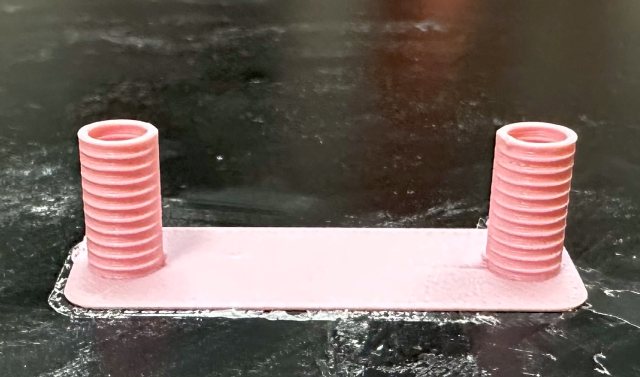
This test generates a retraction tower automatically. The retraction tower is a vertical structure with multiple notches, each printed at a different retraction length. After the print is complete, we can examine each section of the tower to determine the optimal retraction length for the filament. The optimal retraction length is the shortest one that produces the cleanest tower.
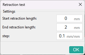
In the dialog, you can select the start and end retraction length, as well as the retraction length increment step. The default values are 0mm for the start retraction length, 2mm for the end retraction length, and 0.1mm for the step. These values are suitable for most direct drive extruders. However, for Bowden extruders, you may want to increase the start and end retraction lengths to 1mm and 6mm, respectively, and set the step to 0.2mm.
Note: When testing filaments such as PLA or ABS that have minimal oozing, the retraction settings can be highly effective. You may find that the retraction tower appears clean right from the start. In such situations, setting the retraction length to 0.2mm - 0.4mm using Orca Slicer should suffice.
On the other hand, if there is still a lot of stringing at the top of the tower, it is recommended to dry your filament and ensure that your nozzle is properly installed without any leaks.
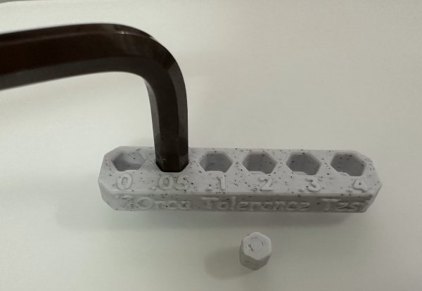
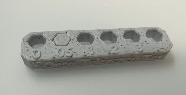
Orca Tolerance Test
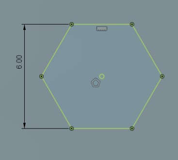
This tolerance test is specifically designed to assess the dimensional accuracy of your printer and filament. The model comprises a base and a hexagon tester. The base contains six hexagon hole, each with a different tolerance: 0.0mm, 0.05mm, 0.1mm, 0.2mm, 0.3mm, and 0.4mm. The dimensions of the hexagon tester are illustrated in the image.
You can assess the tolerance using either an M6 Allen key or the printed hexagon tester.
Advanced Calibration
Max Volumetric speed
This is a test designed to calibrate the maximum volumetric speed of the specific filament. The generic or 3rd party filament types may not have the correct volumetric flow rate set in the filament. This test will help you to find the maximum volumetric speed of the filament.
You will be promted to enter the settings for the test: start volumetric speed, end volumentric speed, and step. It is recommended to use the default values (5mm³/s start, 20mm³/s end, with a step of 0.5), unless you already have an idea of the lower or upper limit for your filament. Select "OK", slice the plate, and send it to the printer.
Once printed, take note of where the layers begin to fail and where the quality begins to suffer. Pay attention to changes from matte to shiny as well.

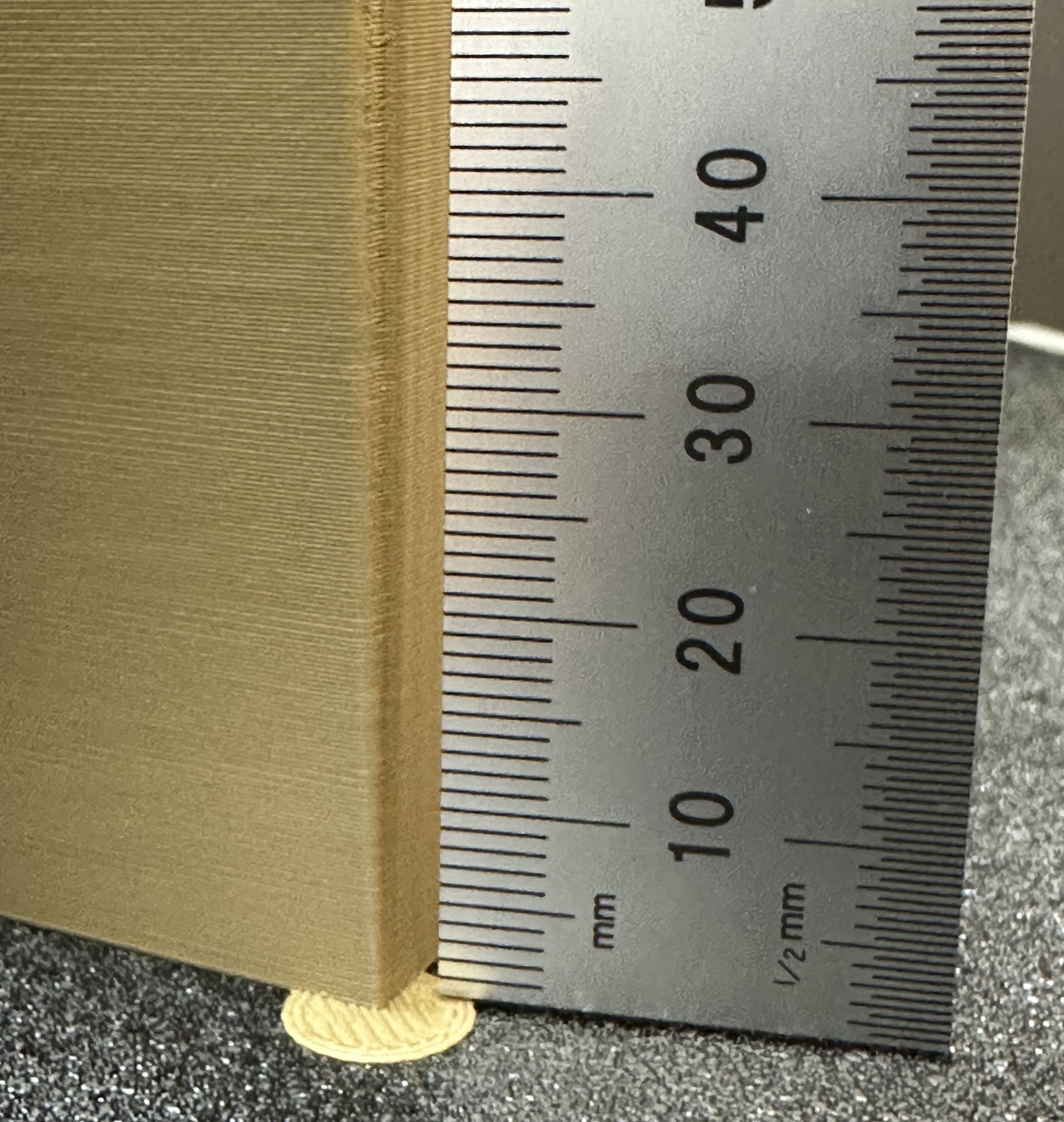
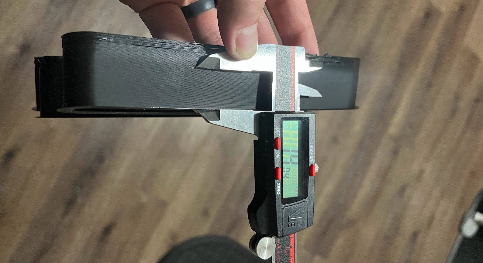
Using calipers or a ruler, measure the height of the print at that point. Use the following calculation to determine the correct max flow value: start + (height-measured * step) . For example in the photo below, and using the default setting values, the print quality began to suffer at 19mm measured, so the calculation would be: 5 + (19 * 0.5) , or 13mm³/s using the default values. Enter your number into the "Max volumetric speed" value in the filament settings.
You can also return to OrcaSlicer in the "Preview" tab, make sure the color scheme "flow" is selected. Scroll down to the layer height that you measured, and click on the toolhead slider. This will indicate the max flow level for your filmanet.
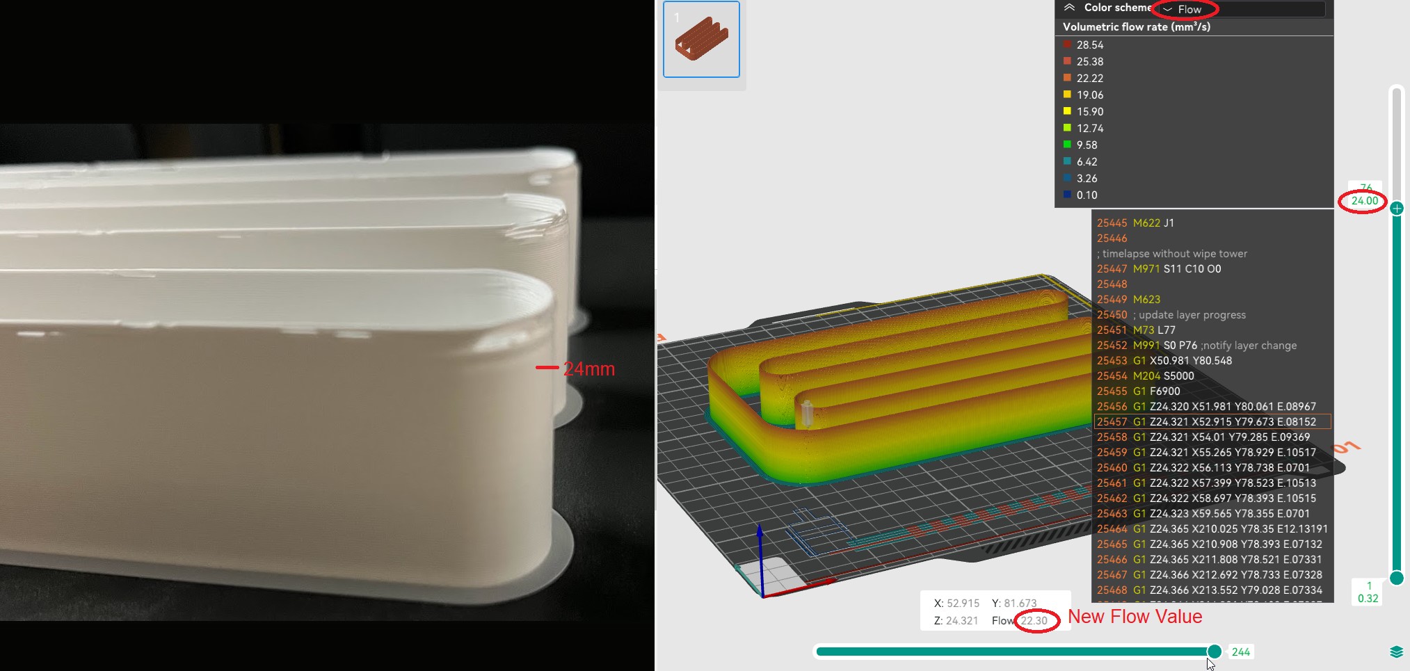
NOTE You may also choose to conservatively reduce the flow by 5-10% to ensure print quality.
Credits:
- The Flowrate test and retraction test is inspired by SuperSlicer
- The PA Line method is inspired by K-factor Calibration Pattern
- The PA Tower method is inspired by Klipper
- *The temp tower model is remixed from Smart compact temperature calibration tower
- *The max flowrate test was inspired by Stefan(CNC Kitchen), and the model used in the test is a remix of his Extrusion Test Structure.
- chapgpt ;)